SONY ST-5140 Owner's Manual June 1972
https://storage.yandexcloud.net/showaaudio-media/images/items/sony-st-5140-manual/main-01.webp197221sony
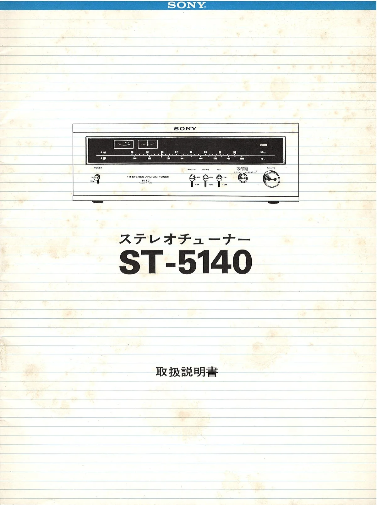
The factory owner’s manual (取扱説明書) for the SONY ST-5140 tuner: a saddle-stitched booklet of 17 pages plus covers, a little smaller than A4, with a cover styled as a sheet of lined notebook paper. The tuner itself sits in the June SONY ES-series leaflet at ¥49,800, paired with the TA-1140 amplifier; this is what came in the box with it.
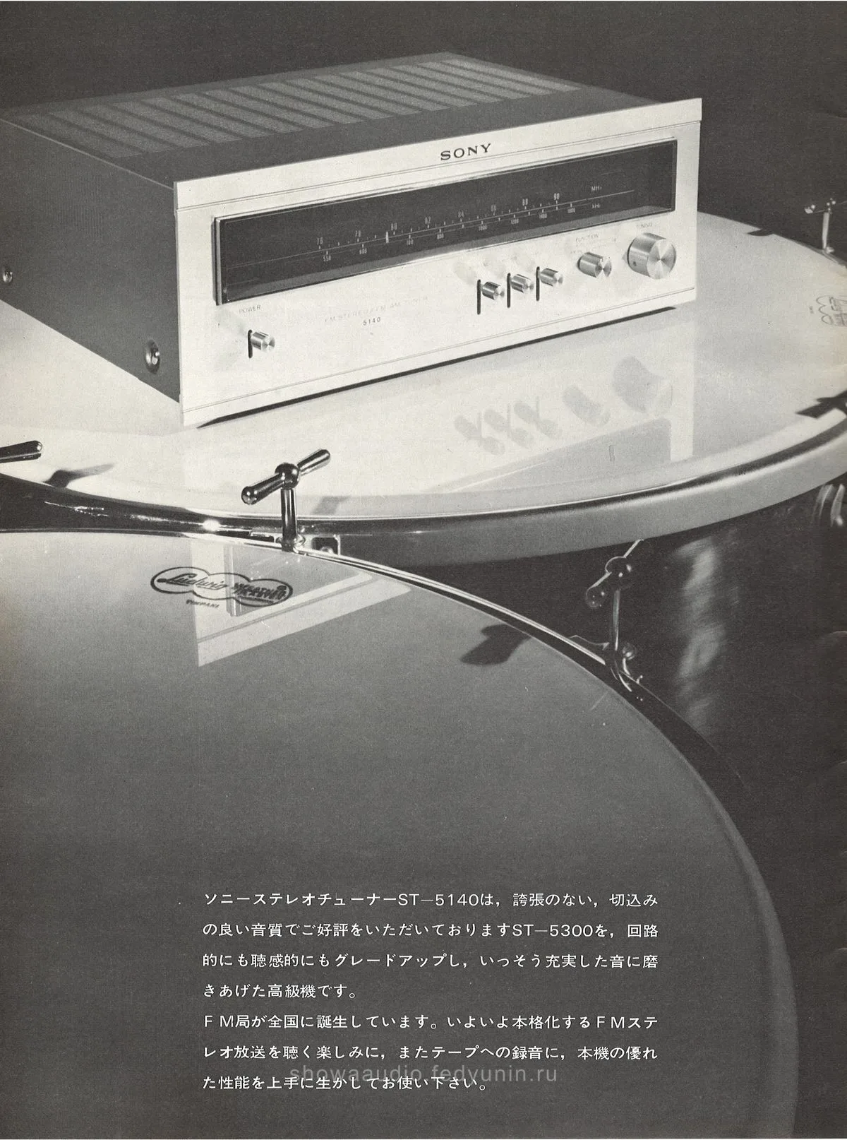
The opening page frames the ST-5140 as a direct grade-up (グレードアップ) of the ST-5300, both in circuitry and in how it sounds. It is photographed sitting on a large drum with a Ludwig hoop, next to a note that FM stations are appearing all over Japan and that the set is also meant for taping broadcasts.
The highlights page lists what SONY was proud of in 1972: a passive RF direct mixer and a new FET circuit in the front end, a 6-element solid-state IF filter with a multi-stage limiter (page 1 says five stages, the block diagram says six, a small inconsistency within one booklet), two meters for tuning, an AM section with a triple-tuned IF transformer and forward AGC against the continuous nighttime “peee” and “sheee” noise, a die-cast panel escutcheon “in the ES-series style” with an extra-long linear FM dial, a 16 kHz low-pass filter against subcarrier leakage for clean recording, and FET muting.
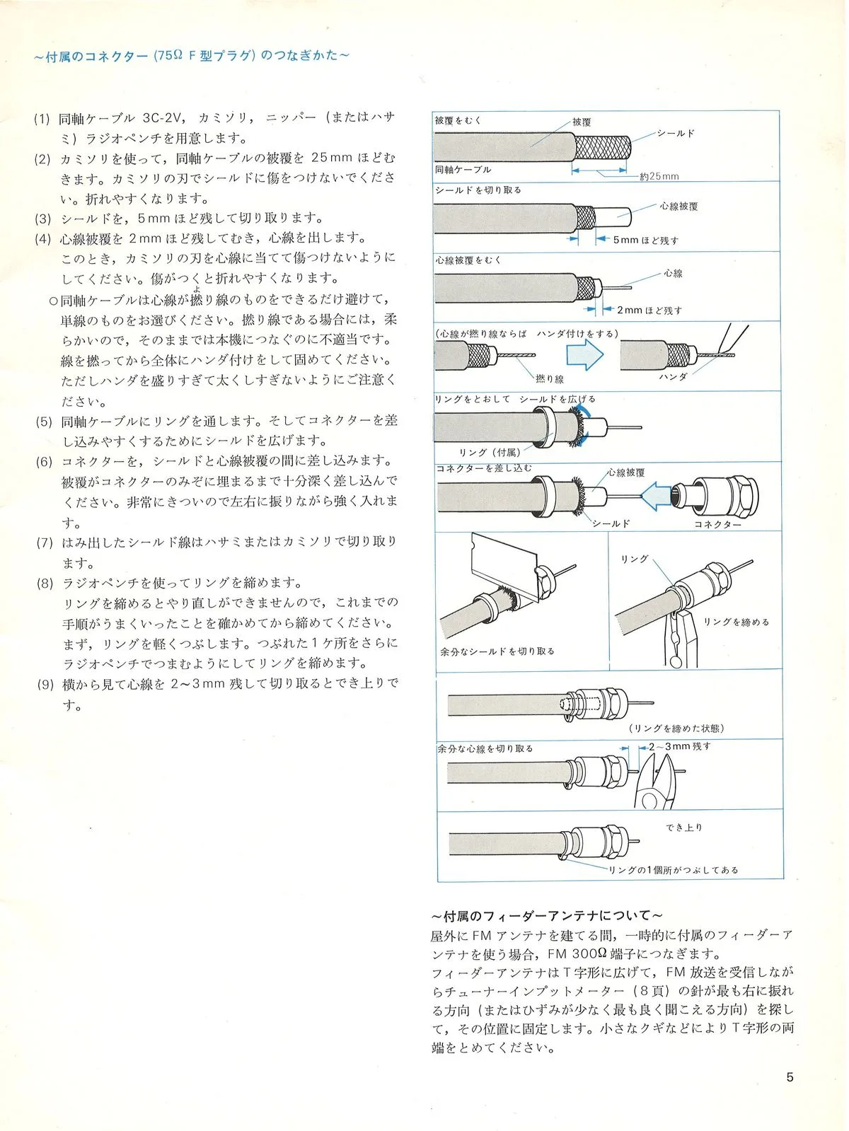
Further on, the manual gets into the practical side, how to do things right. Page 5 is nine steps for terminating 75-ohm 3C-2V coax with the supplied F-connector: razor off 25 mm of jacket without nicking the shield, leave 5 mm of braid and 2 mm of centre insulation, tin a stranded centre conductor solid, slip on the ring, force the connector in while rocking it side to side, crimp the ring with pliers (no do-overs, so check every previous step first) and trim the conductor to 2-3 mm. Separately, how to make a temporary antenna from the supplied ribbon lead on the FM 300Ω terminal: spread it into a T, find the best direction by the input meter and tack the ends down with small nails.
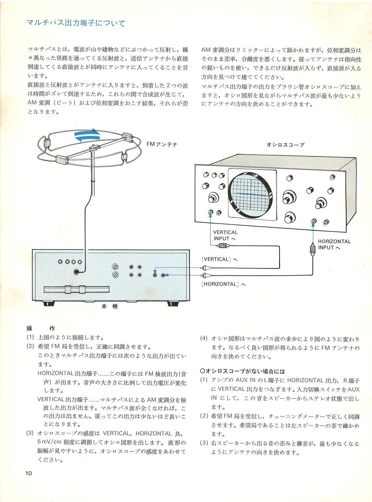
Further in, pages 10-11 cover the multipath output. The rear panel of the ST-5140 has a pair of terminals marked VERTICAL and HORIZONTAL, labelled FM MULTIPATH OUTPUT TO OSCILLOSCOPE: you connect them to a CRT oscilloscope, set the sensitivity to about 5 mV/cm and turn the antenna by the figure on the screen so that reflected waves reach it as little as possible. The manual prints six screen photos, medium and weak field against three multipath states, from an almost straight line to a jagged curve. For anyone without a scope there is a workaround: feed the same outputs into the amplifier’s AUX IN (HORIZONTAL to the left channel, VERTICAL to the right) and turn the antenna by ear until distortion and noise from the right speaker are minimal. Only one antenna is recommended, the loop SONY AN-31 Loopick, about 94 cm across, at ¥3,700.
The specs on page 14 are an ordinary solid-state set for 1972: FM 76-90 MHz, usable sensitivity 2.0 µV IHF, selectivity 80 dB, signal-to-noise 70 dB, capture ratio 1 dB; 2 FETs plus 19 transistors and another 33 diodes in the circuit; AC 100 V, 15 W, cabinet 400 x 149 x 344 mm, 7.2 kg. In the box with the tuner were a ribbon FM antenna, an RK-74 connecting cable, a polishing cloth and that F-connector. A wooden case, the TAC-1N, was sold separately at ¥3,000.
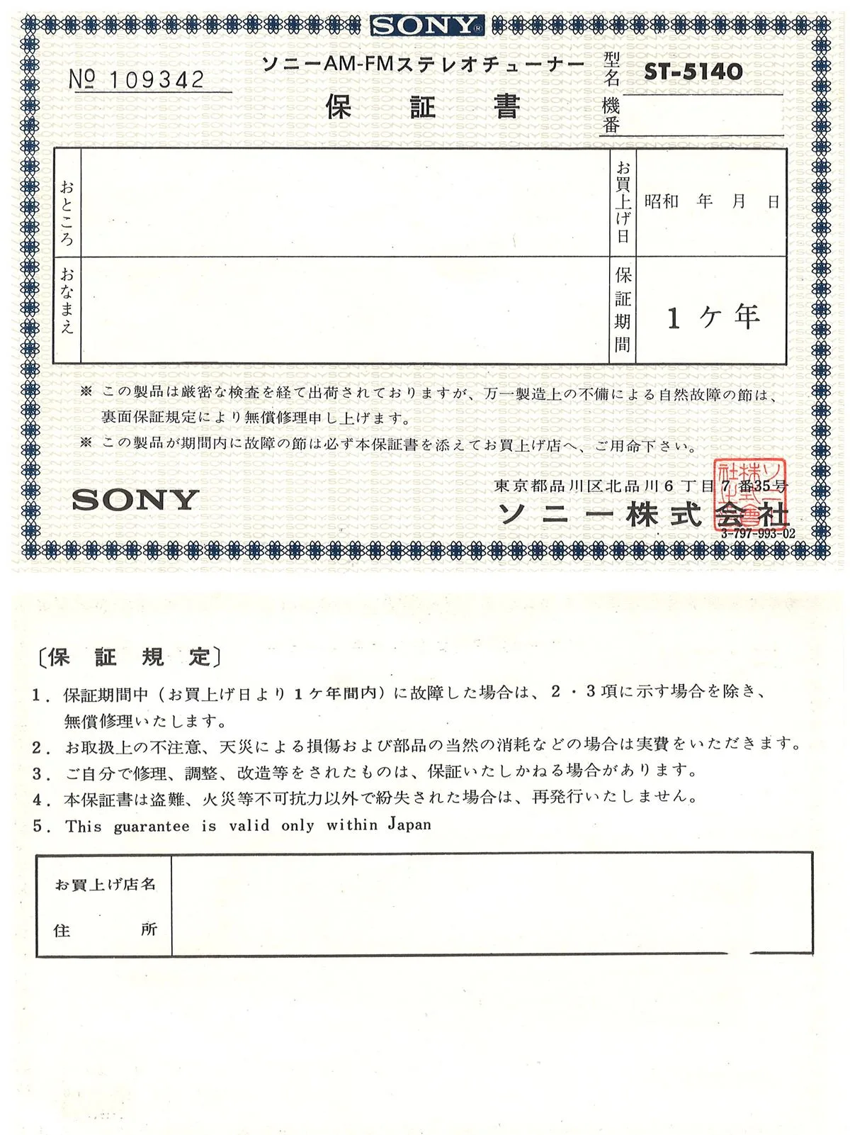
The original warranty card survived inside the manual too (保証書, form 3-797-993-02): serial number No. 109342, a one-year term, the line “This guarantee is valid only within Japan” and SONY’s address in Kita-Shinagawa. The purchase-date field was left blank, which is oddly careless for meticulous Japanese owners - why not fill the whole thing in? Anyway, it means the Japanese owner this stack of SONY catalogues came from did at least buy the tuner, rather than just leafing through the ads.
- パッシブRFダイレクトミキサー方式 - passive RF direct-mixer front end for FM
- 6素子ソリッドステートフィルター - 6-element solid-state IF filter, 80 dB selectivity
- フォワードAGC - forward AGC in the AM section against continuous nighttime noise
- ダイキャストエスカッション - die-cast panel escutcheon in the SONY ES-series style
- マルチパス出力端子 - output for an oscilloscope to watch multipath visually
- FETミューティング - FET muting
| Model | Type | Price |
|---|---|---|
| SONY ST-5140 | AM/FM tuner | ¥49,800 |